The THK LM Guide is capable of receiving loads and moments in all directions that are generated due to the mounting orientation, alignment, gravity center position of a traveling object, thrust position and cutting resistance.
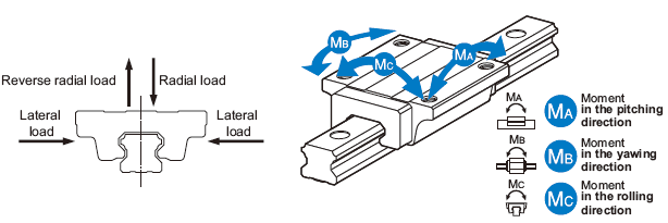
Directions of the Loads Applied on the LM Guide
Calculating an Applied Load
Single-Axis Use
Moment Equivalence
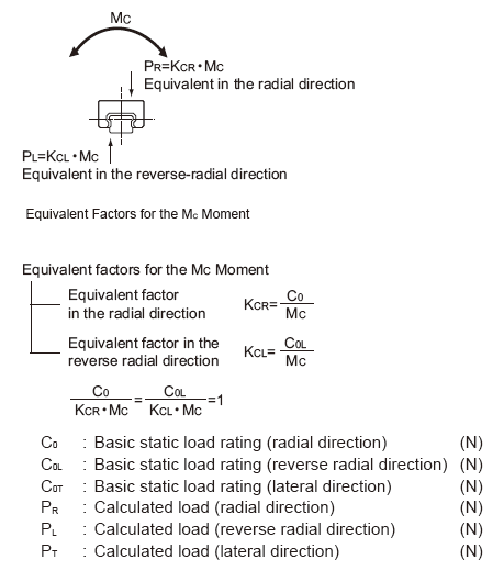
When the installation space for the THK LM Guide is limited, you may have to use only one THK LM block, or double LM blocks closely contacting with each other. In such a setting, the load distribution is not uniform and, as a result, an excessive load is applied in localized areas (i.e., both ends) as shown picture below. Continued use under such conditions may result in flaking in those areas, consequently shortening the service life. In such a case, calculate the actual load by multiplying the moment value by any one of the equivalent-moment factors specified.
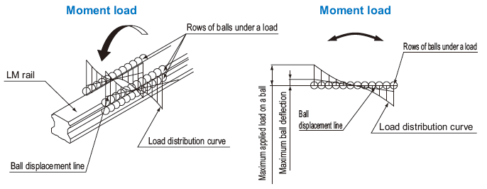
Ball Load when a Moment is Applied
An equivalent-load equation applicable when a moment acts on an LM Guide is shown below.
P: Equivalent load per LM Guide (N)
K: Equivalent moment factor
M: Applied moment (N•mm)
Equivalent Factor
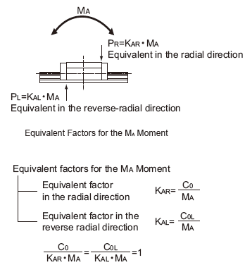
Since the rated load is equivalent to the permissible moment, the equivalent factor to be multiplied when equalizing the M A , M B and M C moments to the applied load per block is obtained by dividing the rated loads in the corresponding directions.
With those models other than 4-way equal load types, however, the load ratings in the 4 directions differ from each other. Therefore, the equivalent factor values for the M A and M C moments also diff er depending on whether the direction is radial or reverse radial.
Equivalent Factors for the M A Moment
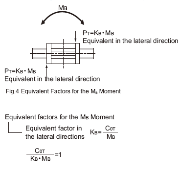
Equivalent Factors for the M B Moment
Equivalent Factors for the M C Moment
Double-axis Use
Setting Conditions
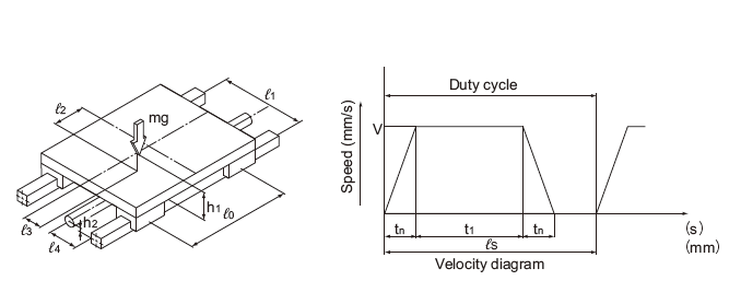
Set the conditions needed to calculate the THK LM system's applied load and service life in hours. The conditions consist of the following items.
- Mass: m (kg)
- Direction of the working load
- Position of the working point (e.g., center of gravity): ℓ 2 , ℓ 3 , h 1 (mm)
- Thrust position: ℓ 4 , h 2 (mm)
- LM system arrangement: ℓ 0 , ℓ 1 (mm) (No. of units and axes)
- Velocity diagram
Speed: V (mm/s)
Time constant: t n (s)
Acceleration: a n (mm/s 2 )
(an = V / tn) - Duty cycle. Number of reciprocations per minute: N 1 (min -1 )
- Stroke length: ℓ s (mm)
- Average speed: V m (m/s)
- Required service life in hours: L h (h)
Condition
Applied Load Equation
The load applied to the THK LM Guide varies with the external force, such as the position of the gravity center of an object, thrust position, inertia generated from acceleration/deceleration during start or stop, and cutting force.
In selecting an THK LM Guide, it is necessary to obtain the value of the applied load while taking into account these conditions.