A linear guide is a machine element that utilizes bearings, which were developed for rotary motion, in order to move heavy objects easily in a straight line. It is referred to as a “recirculating linear ball bearing” or “linear guideway”
This article describes the procedure for handling of Linear guides and installation in machine tools with the prescribed accuracy.
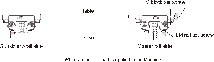
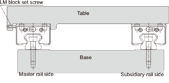
1, How to mount the linear guideWhen an Impact Load is Applied to the Machine and therefore Rigidity and High Accuracy are Required
1.1 Mounting the linear rails
1.1.1 Checking the mounting surface
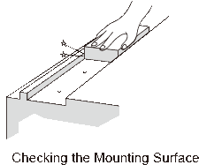
Be sure to remove burr, dent and dust from the mounting surface of the machine to which the linear guide is to be mounted before installing the linear guide.
Please note: Since the Linear Guide is coated with anti-rust oil, remove it from the reference surface by wiping the surface with washing oil before using the guide. Once the anti-rust oil has been removed, the reference surface is prone to getting rusted. We recommend applying low-viscosity spindle oil.
1.1.2 Aligning the Linear rail with the reference-surface
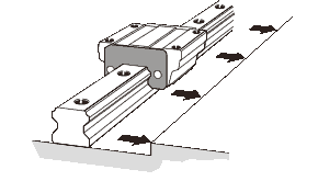
Gently place the linear rail onto the base, and temporarily secure the bolts to the extent that the linear rail lightly contacts the mounting surface.
Please note: The bolts for securing the linear guide must be clean.When placing the bolts into the mounting holes of the linear rail, check if the bolt holes are displaced. Forcibly tightening the bolt into a displaced hole may deteriorate the accuracy.
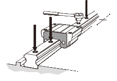
1.1.3 Tightening the set screws
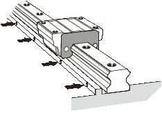
Secure the set screws for the linear rail in order with a tightening force just enough to have the rail closely contact the side mounting surface.
1.1.4 Fully fastening the mounting bolts
Tighten the mounting bolts at the designated torque using a torque wrench.
Please note: To achieve stable accuracy when tightening the LM rail mounting bolts, tighten them in order from the center to the rail ends.
The tables below are recommended Tightening Torque for THK LM Rails (Unit: N.cm)
| Screw model No. | Tightening torque | |
|---|---|---|
| Not hardened | Hardened | |
| M 2 | 17.6 | 21.6 |
| M 2.3 | 29.4 | 35.3 |
| M 2.6 | 44.1 | 52.9 |
| Screw model No. | Tightening torque | ||
|---|---|---|---|
| Steel | Cast Iron | Aluminum | |
| M 2 | 58.8 | 39.2 | 29.4 |
| M 2.3 | 78.4 | 53.9 | 39.2 |
| M 2.6 | 118 | 78.4 | 58.8 |
| M 3 | 196 | 127 | 98 |
| M 4 | 412 | 274 | 206 |
| M 5 | 882 | 588 | 441 |
| M 6 | 1370 | 921 | 686 |
| M 8 | 3040 | 2010 | 1470 |
| M 10 | 6760 | 4510 | 3330 |
| M 12 | 11800 | 7840 | 5880 |
| M 14 | 15700 | 10500 | 7840 |
| M 16 | 19600 | 13100 | 9800 |
| M 20 | 38200 | 25500 | 19100 |
| M 22 | 51900 | 34800 | 26000 |
| M 24 | 65700 | 44100 | 32800 |
| M 30 | 130000 | 87200 | 65200 |
1.1.5 Mount the other rail in the same manner to complete the installation of the linear rails.
1.1.6 Hammer in caps into the bolt holes on the top face of each LM rail until the top of the cap is on the same level as the top face of the rail.
1.2 Mounting the linear blocks
1.2.1 Gently place the table on the linear blocks and temporarily fasten the mounting bolts.
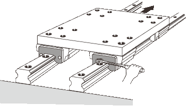
1.2.2 Press the master side linear blocks to the side reference surface of the table using set screws and position the table.
1.2.3 Fully fasten the mounting bolts on the master side and the subsidiary side to complete the installation.
The recommended sequence of tightening the linear blocks
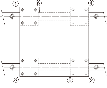
This method saves time in establishing straightness of the linear rail and eliminates the need to machine securing dowel pins, thus to drastically shorten the installation man-hours.
2, Mounting the linear guideWhen the Master LM Rail is not Provided with Set screws
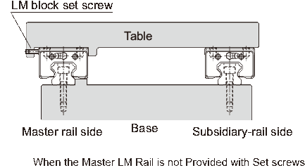
2.1 Mounting the Master Linear Rail
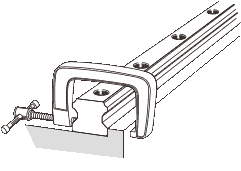
After temporarily fastening the mounting bolts, firmly press the linear rail to the side reference surface at the position of each mounting bolt using a small vice and fully fasten the bolt. Perform this in order from either rail end to the other.
2.2 Mounting the Subsidiary Linear Rail
To mount the subsidiary linear rail in parallel with the master linear rail, which has been correctly installed, we recommend adopting the methods below.
2.2.1 Using a Straight-edge
Place straight-edges between the two rails, and arrange the straight-edges in parallel with the side reference surface of the master linear rail using a dial gauge. Then, secure the mounting bolts in order while achieving straightness of the subsidiary rail with the straight edge as the reference by using the dial gauge.
2.2.2 Using Parallelism of the Table
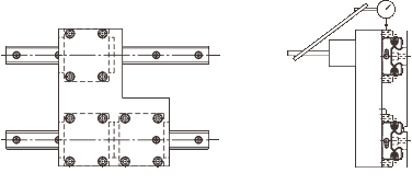
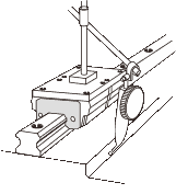
Secure the two linear blocks on the master linear rail with the table (or a temporary table for measurement), and temporarily fasten the linear rail and the linear block on the subsidiary linear rail with the table. Place a dial gauge to the side face of the linear block on the subsidiary rail from the dial stand fixed on the table top, then fasten the bolts in order while achieving parallelism of the subsidiary linear rail by moving the table from the rail end.
2.2.3 Having the Subsidiary Linear Rail Follow the Master Linear Rail
Place the table on the blocks of the correctly mounted master linear rail and the temporarily fastened subsidiary linear rail, and fully fasten the two linear blocks on the master rail and one of the two linear blocks on the subsidiary rail with bolts. Fully tighten the mounting bolts on the subsidiary linear rail in order while temporarily fastening the remaining linear block on the subsidiary linear rail.
2.2.4 Using a Jig
Use a jig to achieve parallelism of the reference surface on the subsidiary side against the side reference surface of the master side from one end of the rail by the mounting pitch, and at the same time, fully fasten the mounting bolts in order.
3, Mounting the linear guideWhen the Master LM Rail Does not Have a Reference Sur-face
3.1 Mounting the Master Linear Rail
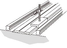
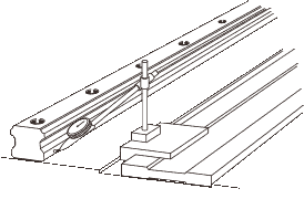
3.1.1 Using a Temporary Reference Surface
You can temporarily set a reference surface near the linear rail mounting position on the base to achieve straightness of the linear rail from therail end. In this method, two linear blocks must be joined together and attached to a measurement plate.
3.1.2 Using a Straight-edge
After temporarily fastening the mounting bolts, use a dial gauge to check the straightness of the side reference surface of the linear rail from the rail end, and at the same time, fully fasten the mounting bolts.
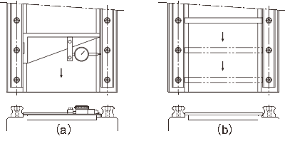
4, Measuring Accuracy after Linear guides Installation
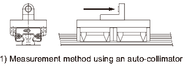
When measuring running accuracy of the LM block, stable accuracy can be obtained by securing two LM blocks on an inspection plate.
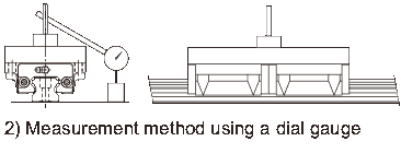
When using a dial gauge, we recommend placing the straight-edge as close as possible to the LM block in order to perform accurate measurement.