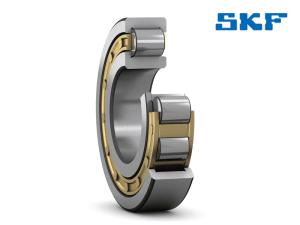
SKF single row cylindrical roller bearings are available in many designs, series and sizes. The major design differences between the bearings presented in this section are in:
- the cage design and material
- the configuration of the inner and outer ring flanges
Features
1, Low friction
The open flange design, together with the roller end design and surface finish, promote lubricant film formation resulting in lower friction and higher axial load carrying capacity.
2, Long service life
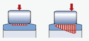
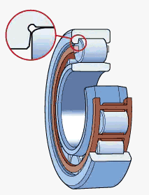
The logarithmic roller profile reduces edge stresses at the roller/raceway contact and sensitivity to misalignment and shaft deflection.
3, Enhanced operational reliability
The surface finish on the contact surfaces of the rollers and raceways supports the formation of a hydrodynamic lubricant film.
4, Separable and interchangeable
The separable components of SKF cylindrical roller bearings are interchangeable. This facilitates mounting and dismounting, as well as maintenance inspections.
5, High speed capability
The cage designs are suitable for high speeds, rapid accelerations and peak loads.
SKF single row cylindrical roller bearings' design
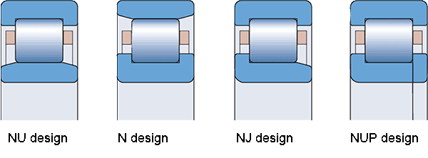
NU design bearings
- Have two integral flanges on the outer ring and no flanges on the inner ring
- Can accommodate axial displacement of the shaft relative to the housing in both directions
- Can be used together with an appropriate angle ring to stabilize the bearing in the axial direction.
N design bearings
- Have two integral flanges on the inner ring and no flanges on the outer ring
- Can accommodate axial displacement of the shaft relative to the housing in both directions
NJ design bearings
- Have two integral flanges on the outer ring and one on the inner ring
- Can accommodate axial displacement of the shaft relative to the housing in one direction only
- Are used to locate the shaft axially in one direction
- Can be used together with an appropriate angle ring to stabilize the bearing in the other axial direction
NUP design bearings
- Have two integral flanges on the outer ring and one integral flange and one non-integral flange, i.e. a loose flange ring, on the inner ring
- Are used to locate the shaft axially in both directions
Cages for SKF single row cylindrical roller bearings
SKF single row cylindrical roller bearings are fitted with one of the cages shown below
| Cage type | Window-type
|
Window-type, roller centred |
Window-type, inner or outer ring centred (depending on bearing design) |
Riveted
|
Window-type, inner or outer ring centred (depending on bearing design) |
Riveted
|
|---|---|---|---|---|---|---|
| Material |
|
Stamped steel |
Machined brass | Machined brass | Machined light alloy | Machined light alloy |
| Suffix |
|
|
|
|
|
|
| Metric bearing |
Standard | Standard | Standard | Standard | Standard | Standard |
| Inch bearing |
– | Standard | – | Standard | – | – |
SKF cylindrical roller bearing date
- Dimension standards
- Boundary dimensions: ISO 15
- Tolerances
-
- Normal dimensional tolerance
- P6 run-out
- Radial internal clearance
- Normal, C3
- Axial internal clearance
- Guideline values:
- NUP design
- NJ design with an HJ angle ring
- 10, 18, 19, 2, 3 and 4 series: ≈ the radial internal clearance
- 22, 23, 29 and 39 series: ≈ 2/3 the radial internal clearance
- Permissible misalignment
-
- 10, 12, 18, 19, 2, 3 and 4 series: ≈ 4 minutes of arc
- 20, 22, 23, 29 and 39 series: ≈ 3 minutes of arc
The values are not valid for bearings of the NUP design or the NJ design with an HJ angle ring.
Designation system for SKF cylindrical roller bearings
The desinations of SKF rolling bearings follow a system that may consist of a basic designation with or without one or more prefixes and/or suffixes. (please refer to SKF bearing designation system.)
Prefixes
- L
- Separate inner or outer ring of a separable bearing
- R
- Inner or outer ring with roller and cage assembly of a separable bearing
Suffixes
Internal design
- A
- Deviating or modified internal design
- EC
- Optimized internal design incorporating more and/or larger rollers and with modified roller end / flange contact
External design
- k
- Tapered bore, taper 1:12
- N
- Snap ring groove in the outer ring
- NR
- Snap ring groove in the outer ring, with associated snap ring
- N1
- One locating slot (notch) in one outer ring side face
- N2
- Two locating slots (notches) in one outer ring side face, 180° apart
Cage design
- FR
- Pin-type steel cage, pierced rollers
- J
- Stamped steel cage, roller centred
- L
- Machined light alloy cage, roller centred
- LA
- Machined light alloy cage, outer ring centred
- LB
- Machined light alloy cage, inner ring centred
- LL
- Machined light alloy cage, window-type, inner or outer ring centred (depending on bearing design)
- M
- Machined brass cage, roller centred
- MA(S)
- Machined brass cage, outer ring centred. The S indicates a lubrication groove in the guiding surface.
- MB
- Machined brass cage, inner ring centred
- ML
- Machined brass cage, window-type, inner or outer ring centred (depending on bearing design)
- MP
- Machined brass cage, window-type, inner or outer ring centred (depending on bearing size)
- MR
- Machined brass cage, window-type, roller centred
- P
- Glass fibre reinforced PA66 cage, roller centred
- PA
- Glass fibre reinforced PA66 cage, outer ring centred
- PH
- Glass fibre reinforced PEEK cage, roller centred
- PHA
- Glass fibre reinforced PEEK cage, outer ring centred
Materials, heat treatment
- HA1
- Case-hardened inner and outer rings
- HA2
- Case-hardened outer ring
- HA3
- Case-hardened inner ring
- HB1
- Bainite-hardened inner and outer rings
- HB3
- Bainite-hardened inner ring
- HN1
- Inner and outer rings with special surface heat treatment
Accuracy, clearance, preload, quiet running
- CN
- Normal radial internal clearance; only used together with an additional letter that identifies a reduced or displaced clearance range
- C2
- Radial internal clearance smaller than Normal
- C3
- Radial internal clearance greater than Normal
- C4
- Radial internal clearance greater than C3
Bearing sets, matched bearings
- DR
- Set of two matched bearings
- TR
- Set of three matched bearings
- QR
- Set of four matched bearings
Stabilization
- S1
- Bearing rings heat stabilized for operating temperatures ≤ 200 °C (390 °F)
- S2
- Bearing rings heat stabilized for operating temperatures ≤ 250 °C (480 °F)
Lubrication
- W33
- Annular groove and three lubrication holes in the outer ring