The main dimensions of rolling bearings are the key dimensions of a rolling bearing. They include
- the bore diameter (d)
- the outside diameter (D)
- the width or height (B, C, T or H)
- the chamfer dimensions (r)
It is necessary to know all of these dimensions when mounting a bearing on a shaft and in a housing.
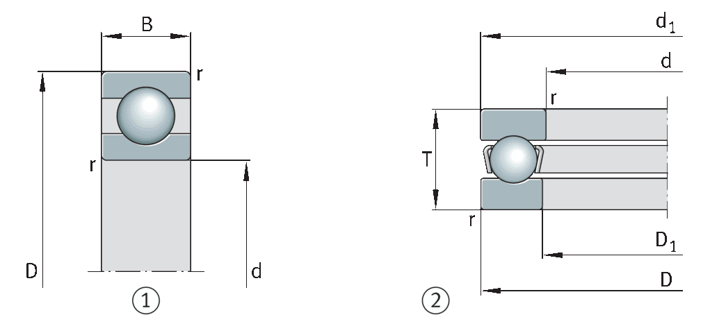
2, Thrust bearing
The boundary dimensions for metric bearings are standardized in the ISO general plans. Most rolling bearings follow ISO standard dimensions, which is a prerequisite to enable interchangeability. The main dimensions of metric rolling bearings are defined in the following ISO dimension plans:
- ISO 15:2017 for radial rolling bearings, excluding single row needle roller bearings, insert bearings and tapered roller bearings
- ISO 355 : 2007 for tapered roller bearings
- ISO 104 : 2015 for axial bearings
ISO dimension for rolling bearings
Standard dimensions
Experience has shown that the predominant proportion of all bearing arrangement tasks can be fulfilled using bearings with standard dimensions, which are contained in ISO dimension plans.
Advantages of dimension plans
The dimension plans are valid for different bearing types. Standard rolling bearings of different types can thus be manufactured to the same external dimensions. As a result, a designer working on the same design envelope can make a selection between bearings of several types with the same external dimensions.
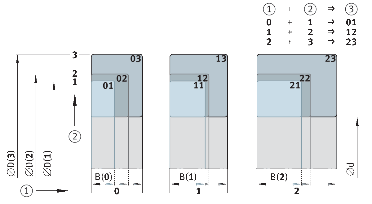
Several outside diameters/ width dimensions are assigned to one bearing bore
In the dimension plans, one bearing bore is allocated several outside diameters and width dimensions. In this way, it is possible to design several bearings of the same type that, for the same bore, exhibit different load carrying capacities. The development of new bearing series and individual new rolling bearings in accordance with the dimension plans has considerable advantages for users and manufacturers.
The ISO general plan for radial bearings provides several series of standardized outside diameters for every standard bore diameter. They are called diameter series and are numbered 7, 8, 9, 0, 1, 2, 3 and 4 (in order of increasing outside diameter). Within each diameter series, different width series exist (width series 8, 0, 1, 2, 3, 4, 5 and 6 in order of increasing width).
For thrust bearings, height series are used instead of width series. Height series are numbered 7, 9, 1 and 2.
Bearing series are described using numbers. Width and diameter series are described using numbers. In the case of radial bearings in accordance with ISO 15, these are as follows:
Width series
For width series, the numbers 8, 9, 0, 1, 2, 3, 4, 5, 6, 7
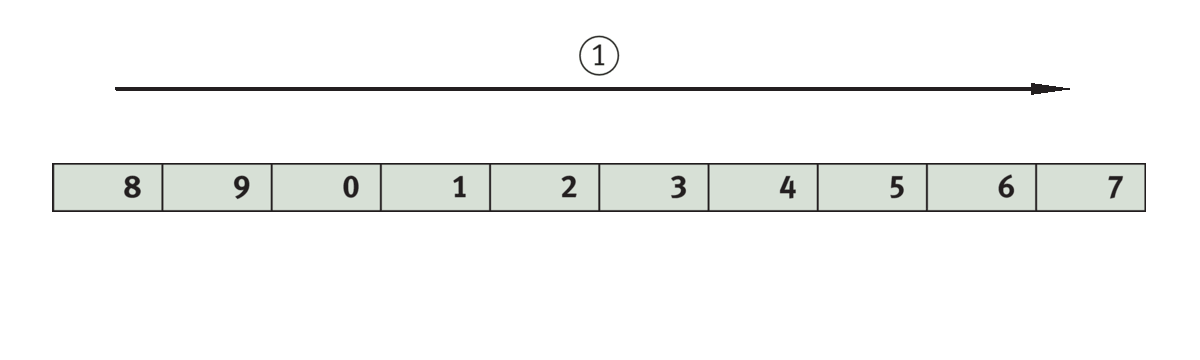
Identification of width series. Width series
Diameter series
For the identification of diameter series, the numbers 7, 8, 9, 0, 1, 2, 3, 4, 5

Identification of diameter series. Diameter series
Dimension series
The dimension series is created from the width series and the diameter series
The specific number of the width and diameter series, when combined, identifies the dimension series. When this table is used, for example, for a radial bearing of the width series 2 and the diameter series 3, this gives the dimension series 23. And if the bearing bore code is then added, the bearing size is completely defined.
Dimension series for radial bearings (excluding tapered roller and needle roller bearings)
| Width series – increase in cross-sectional width | |||||||||||
|---|---|---|---|---|---|---|---|---|---|---|---|
| 8 | 9 | 0 | 1 | 2 | 3 | 4 | 5 | 6 | 7 | ||
| Diameter series – increase in cross-sectional height | 5 | ‒ | ‒ | ‒ | ‒ | ‒ | ‒ | ‒ | ‒ | ‒ | ‒ |
| 4 | ‒ | ‒ | 04 | ‒ | 24 | ‒ | ‒ | ‒ | ‒ | ‒ | |
| 3 | 83 | ‒ | 03 | 12 | 23 | 33 | ‒ | ‒ | ‒ | ‒ | |
| 2 | 82 | ‒ | 02 | 12 | 22 | 32 | 42 | 52 | 62 | ‒ | |
| 1 | ‒ | ‒ | 01 | 11 | 21 | 31 | 41 | 51 | 61 | ‒ | |
| 0 | ‒ | ‒ | 00 | 10 | 20 | 30 | 40 | 50 | 60 | ‒ | |
| 9 | ‒ | ‒ | 09 | 19 | 29 | 39 | 49 | 59 | 69 | ‒ | |
| 8 | ‒ | ‒ | 08 | 18 | 28 | 38 | 48 | 58 | 68 | ‒ | |
| 7 | ‒ | ‒ | ‒ | 17 | 27 | 37 | 47 | ‒ | ‒ | ‒ | |
2, Diameter series
3, Dimension series
Dimension plan for metric tapered roller bearings to ISO 355
Tapered roller bearings can generally also be classified in the dimension plans to ISO 355. The dimension series are designated in these by a combination of three symbols.
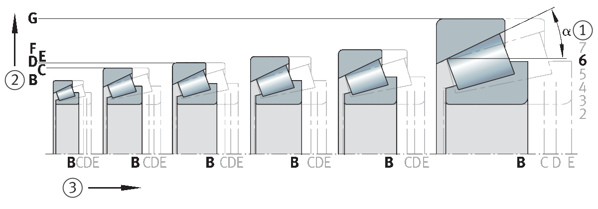
1, Contact angle series (range of contact angles)
2, Diameter series
3, Width series